While all ISO containers are the same size dimensionally and the minimum load performance of the components
is standardized via the ISO, the actual geometry of components, including walls and corner posts, is not standardized.
Manufacturers of different containers offer many different designs. All surpass the ISO test loads, but slight variations exist,
in side and end wall corrugation patterns, floor levels, floor joist type, and even side rail profile.
GET THE COMPLETE SET OF BLUEPRINTS FOR A SHIPPING CONTAINER
SENT DIRECTLY TO YOU EMAIL ADDRESS
Deconstructing a shipping container is a good way to understand the underlying engineering principals, and,
if you plan to incorporate used containers as an engineered element in your structural plans you will need to
explain the materials, construction, strength and load capacities of the various container elements, in
engineering terms, right there on your plans.The simple truth is that these blueprints are a vital way to prove that your shipping container structure is capable of meeting
the same load requirements as specified for traditional residential construction. When you can do this you are home free as long as
your projects it meets all other relevant requirements as well. In the eyes of the building department’s engineers
this will deem the structure safe for occupancy.
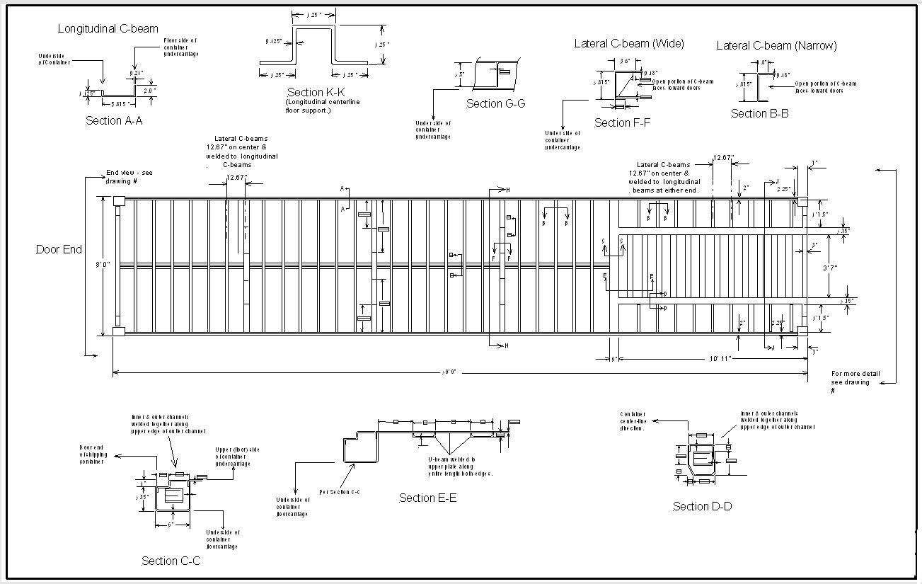
A typical ISO Series1 container consists of several elements, and each element’s ability to bear a load differs.
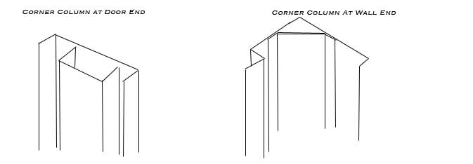
The main structural components of a shipping container are the four columns, which make up the corners
of the container. These are of 2 types, as shown in the diagram below. Steels used in corner posts typically
correspond to the specification ASTM A-572, a low alloy columbium or vanadium steel, with a yield stress of
47,000 psi, and an ultimate stress of 70,000 psi. The wall corner columns are made of 6mm pressed steel
shapes welded together along the entire length. The door end column is a hot rolled channel 113x40x10mm
that is welded to the 6mm plate.
In addition to resisting collapse, the corner post must also work at a compressive stress that is below the yield of the material. Corner posts will yield at a stress of 47,000 psi. Therefore, the minimum cross sectional area for resisting the corner post loads is A = 190,840/47,000 = 4.05 in2. The Door End post has a collapse load which is less than the load required by the ISO standard, and therefore must rely on interaction with the walls and doors of the container to produce the necessary load-bearing capacity. Adding a 3-inch wide strip of adjacent container sidewall (3.6 mm thick) and a 2-inch wide strip of door panel (2 mm thick) will form a column of considerably higher strength (252,000 lbs) than the original profile (175,000 lbs) alone.
The corner fittings at both ends of all 4 columns are an integral part of the load-bearing column in the container.The corner fitting of the bottom container in a stack must withstand the weight of the containers stacked above it, plus the weight of the bottom container itself. The maximum load, which a single corner fitting must take in normal use, would be,
P = 190,480 + (52,800/4) = 203,680 lbs
Corner fittings are typically cast and machined from A-216 steel, which has a minimum specified yield stress of 40,000 psi. Therefore, under maximum load, a corner fitting of the cross section shown below operates with a safety factor on yield of nearly 2.0
The AISC Steel Construction Code uses a safety factor of 2 for column loading; this conservative design in civil structures is necessary because there is typically no load-testing of the parts; they are designed, manufactured, and set in place with only the calculation and fabrication standards serving as proof of merit.
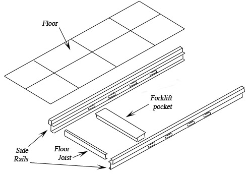
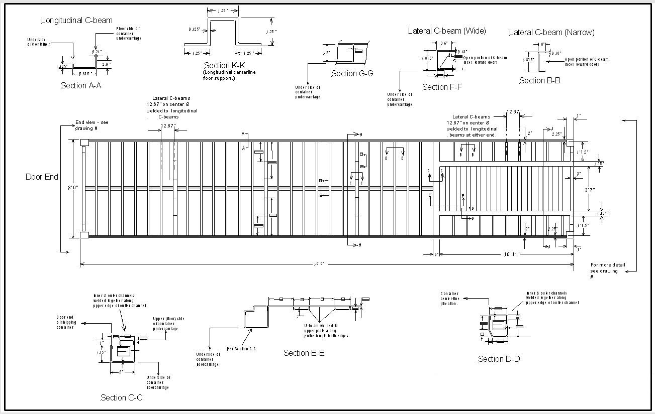
BASE ASSEMBLY
The ISBU base assembly consists of two side rails, which are connected by a series of perpendicular steel floor joists welded between the side rails every 12 inches. Inter spaced between the jousts on 20’ containers will be built-in forklift pockets. 40’ containers may have a gooseneck attachment pocket in the front of the unit, but generally not forklift pockets.
Once the side rails and joists are assembled a sheathing of ¾” or 1” marine plywood is secured to the floor joists with screws.
Deconstructing a shipping container is a good way to understand the underlying engineering principals, and,
if you plan to incorporate used containers as an engineered element in your structural plans you will need to
explain the materials, construction, strength and load capacities of the various container elements, in
engineering terms, right there on your plans.The simple truth is that these blueprints are a vital way to prove that your shipping container structure is capable of meeting
the same load requirements as specified for traditional residential construction. When you can do this you are home free as long as
your projects it meets all other relevant requirements as well. In the eyes of the building department’s engineers
this will deem the structure safe for occupancy.
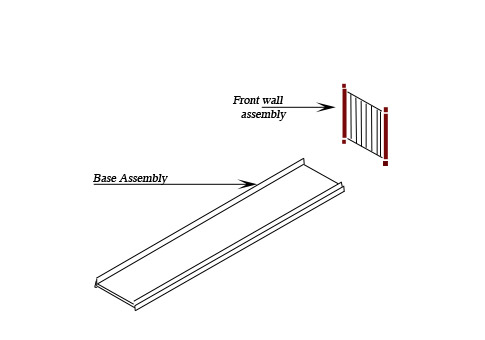
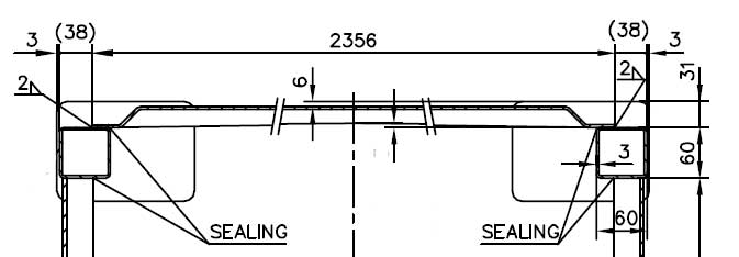
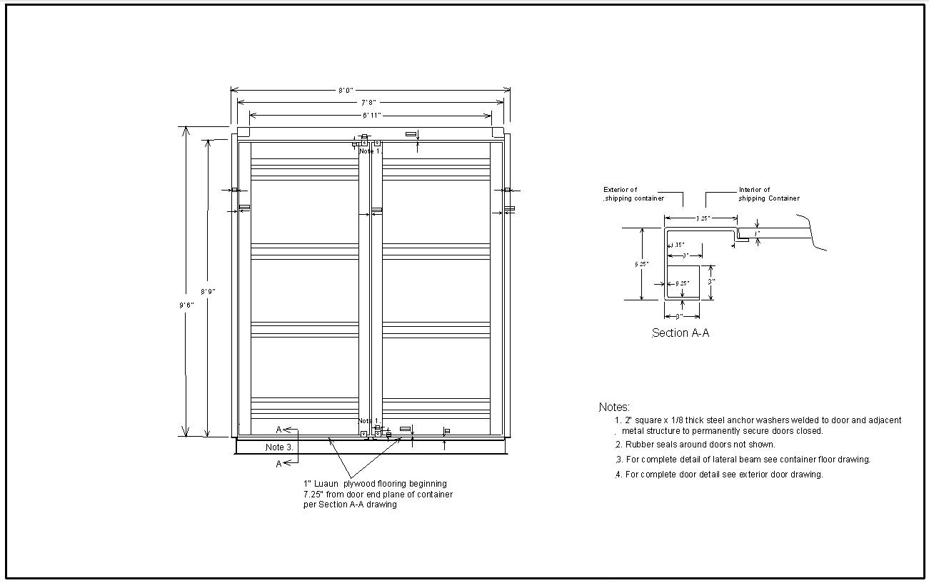
FRONT WALL ASSEMBLY
Once this base is assembled the front-end wall assembly, which consists of a front sill, two corner columns and four corner fittings (one welded to each end of each column), is welded to the base. The end wall panel is continuously welded in place between the columns and front sill. The columns and corner fitting are marked in red as the load bearing members.
The corner columns (marked as red) of the end wall assembly are tested to a load of 190,480 lbs. They are usually made of steel typically corresponding to ASTM A-572, with a yield stress of 47,000 psi, and an ultimate stress of 70,000 psi.
The red squares in the diagram above represent the corner fittings, which are tested to 203,680 lbs. Corner fittings are typically cast and machined from A-216 steel, which has a minimum specified yield stress of 40,000 psi.
Both front and rear columns have adequate cross sectional area from the standpoint of compressive stress. However, the Door End column has a collapse load, which is less than the load required by the ISO standard, and therefore must rely on interaction with the walls and doors of the container to produce the necessary load-bearing capacity, however in our applications this shouldn’t be a factor since the critical load on the column alone is approx. 175,000 lbs. Retain the cargo doors as part of the structure and strength increases dramatically, to a critical load of approximately 252,000 lbs.
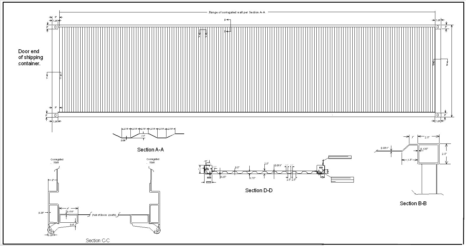
SIDE WALLS
Once the two end assembles are in place the side walls, which are vertically corrugated steel, usually 3.6 mm thick, can be perimeter welded to the two bottom rails and four corner columns.
Because the corner posts of all containers are known to have been tested to the load stipulated by ISO 1496 with no failures occurring at a load that is less than the test load, a lower safety factor of about 1.5 is adequate for a stack of containers on land.
ROOF
A top channel along the length of the sidewalls connects the upper beams to the two end sections, and provides anchor point where the steel roof sections are welded in place.
As you can see it's pretty obvious why you cannot just stack containers any way you want. The strength for stacking is in the corner columns, the roof and side walls aren't designed to support the weight of an entire container without adding support bracing or additional columns as you will see in the Examples Section.
Scroll down for next chapter
Deconstructing a shipping container is a good way to understand the underlying engineering principals, and,
if you plan to incorporate used containers as an engineered element in your structural plans you will need to
explain the materials, construction, strength and load capacities of the various container elements, in
engineering terms, right there on your plans.
The simple truth is that these blueprints are a vital way to prove that your shipping container structure is capable of meeting
the same load requirements as specified for traditional residential construction. When you can do this you are home free as long as
your projects it meets all other relevant requirements as well. In the eyes of the building department’s engineers
this will deem the structure safe for occupancy.