This plan was envisioned as a small vacation house, ideally on a beach somewhere tropical, like Belize, or perhaps even on the Gulf Coast of Texas. It may be a little ambitious with 1 bedroom and 2 baths in 2 stories, but I decided to use it because it is a good example for learning the design rules and methods for cantilevering and stacking containers
Because it was designed for a temperate or tropical climate I didn’t include HVAC, I planned to use only through the wall AC like you usually see in tropical environments. I made a couple of quick sketches of a very basic floor plan consisting of one 40’ ISBU and three 20” containers for a total of 800 sq ft under roof. I envisioned a patio or deck on both levels to expand the living area outdoors to take advantage of the climate.
Conceptual Layout
Preliminary Load Path Analysis
Foundation Analysis for Second Floor Exterior Wall Cutouts
Interior Wall Plan Cabinets and Fixtures Mechanicals
Roofing Plan
Exterior Cladding
I began with a couple of quick sketches of what I thought would be a simple layout that was easy to build using six containers.
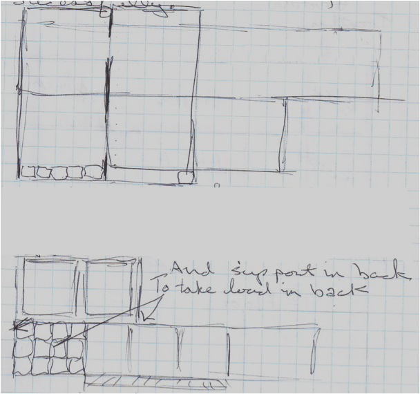
Figure 1 Quick elevation view of container placement
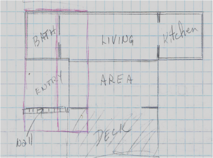
Figure 2 Preliminary floor plan sketch
Even in the 2 preliminary sketches I can see some structural issues with the second story, the upper floor containers won’t be positioned properly to provide a load path from the second level through the first level and to the foundation, so I am probably going to need to kick the upper floor back a little to provide a place for vertical posts to support the outer corners. At the other end I placed a stone masonry wall to provide support for the second floor, which will also separate the entry from the back patio area and allows for the ability to add more square footage by enclosing the entry area and making interior entry as part of the house rather than just a porch, which also adds 64 sq. ft to the area of the house
Another issue I can see is a possible lack of space for a flight of stairs to reach the second floor. So this plan is going to need a more detailed look at the structural aspects before a decision is made on developing the design further. I don’t want to put too much effort into the design if I can’t meet the basic structural requirements of a good design as discussed earlier.
When the modeling is finished we will be able to look underneath the entire structure and adjust each floor platforms to allow additional support posts to be added for the upper floor. As you will see in the next picture I’m modeling the bare structural basics of a typical ISBU in this stage and focusing entirely on making sure that each ISBU element has an acceptable load path. I’ll use the CAD to create a floor platform to represent each ISBU in the plan. On each floor platform will be four posts colored red to represent them as load bearing corner posts.
Since the floor platforms are going to be moved around quite a bit to work out the structural issues I’m going to omit the pier foundation elements for now. When the modeling is finished we will be able to look underneath the entire structure and adjust each floor platforms to allow additional support posts to be added for the upper floor.
As you will see in the next picture I’m modeling the bare structural basics of a typical ISBU in this stage and focusing entirely on making sure that each ISBU element has an acceptable load path.

Figure 3 - 3D CAD view from below, looking up at structure
This view looking up provides some insight to the problems with this design; for starters, the upper floor is not supported properly, of the two upper container's eight corners, only one would be considered properly positioned directly above the ISBU corner below it. Of course, since they are stacked perpendicular to the lower units they will never line up as they were intended so we will take the necessary steps to add additional vertical load support.
Taking advantage of CAD’s ability to rotate the model in space I’m going to play with some variations to try and come up with some solutions.
Offsetting the containers on the upper floor will allow the end to overhang just enough to get a column or post under each corner for support. On the other side I added a wall to support both ISBUS. Now we have an upper floor that is supported entirely by the wall and the steel posts in the back. The first floor containers are not bearing any of the weight of the upper floor.

Figure 4 - The upper floor is now fully supported by a wall and 4 posts
Now we have two floor levels, with each being structurally supported independent of the other. Anchoring the upper containers should present no real problems as both the posts and the wall can incorporate the positive locking twist locks made especially to connect with the containers corner fittings. The image below shows the elevation view for a straight on perspective.
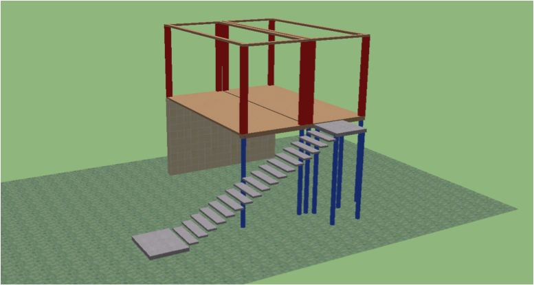
Figure 5 - Elevation View
So that’s the first problem solved, but I’m still not sure about where there is going to be room for stairs. One solution could be to build an exterior stairwell that is enclosed; another possibility is a small spiral staircase. The spiral stairs may create additional challenges, since it would require cutting through the second story floor and some of the floor joists. In addition it would cause the loss of about 16 sq. ft. of floor space if the opening is 4’X4’.
I’m leaning towards cutting a door in the back wall of the 40’ container, and then, just outside the wall, build a covered stairway that leads to the second floor with a left turn on the top landing leading to a door opening to the second floor.
It would not be very hard to frame in wood and it will save precious floor space. The exterior cladding will cover the framing and incorporate the staircase protrusion into the overall mass of the structure helping to break up the plane of the long wall and adding some interest.
But before I do that I want to elevate each of the structural elements by 12 inches and place the foundation piers at the corners of the ground units to support them while also creating a crawlspace for access to the underneath of the structure. The structural plan is color coded with blue representing foundation members and red representing the load bearing members of the containers.
The plan view now shows all of the structural elements supporting the vertical load. But there remains the issue of lateral loads such as winds, which will exert a pushing force on the upper story, causing the supporting posts to flex and possibly collapse. To remedy this will require structural elements connecting the upper and lower floors.
I’m feeling more confident of the structural design now because every container corner will be supported by a foundation element, either a concrete pier, or steel post, or masonry wall, and the second floor is supported independently of the ground floor as seen in this plan view and the lateral loads are accounted for.
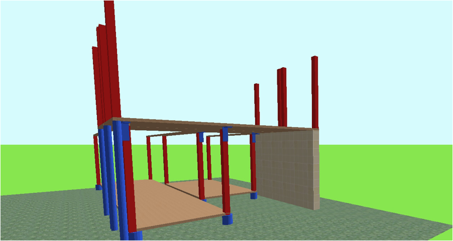
Figure 6 - Blue anchors will transfer upper floor loads to ground.
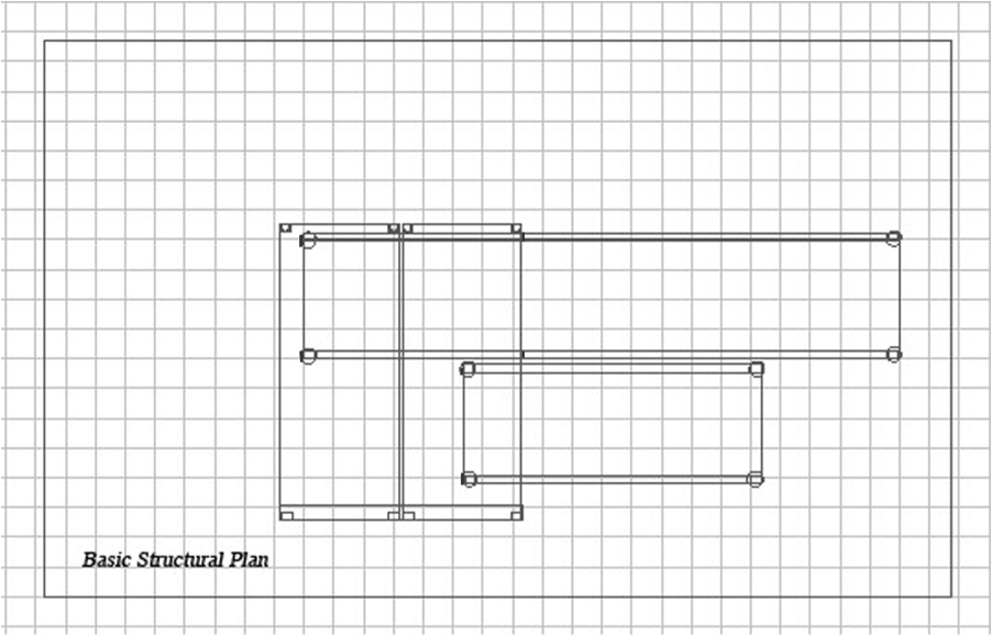
Figure 7 - Structural elements, as seen in plan view
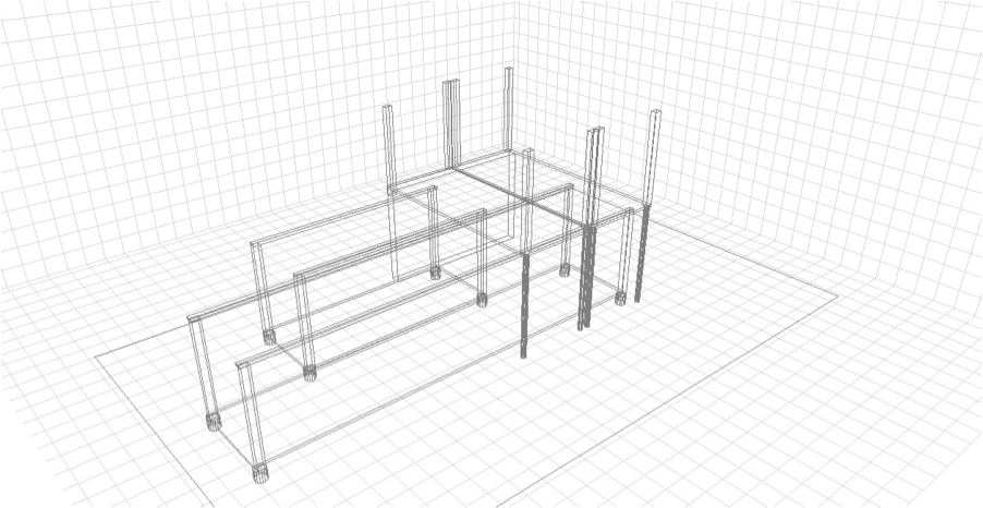
Figure 8 - The perspective view makes it easier to visualize load paths
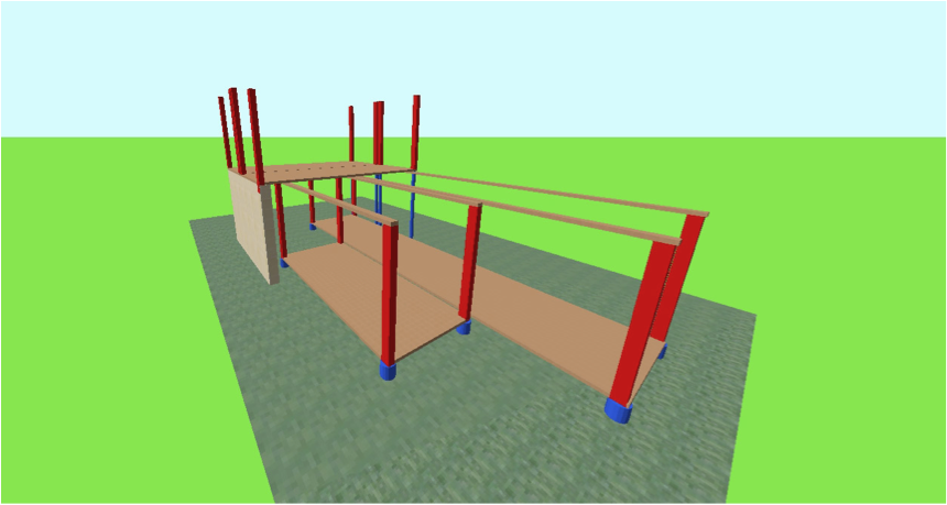
Figure 9 - Adding texture and color to show load paths
I’m making a few other adjustments. Since the second floor has independent support now I can shift it slightly so the long side will overhang the first floor some. I’m also going to shift the ground floor 20’ ISBU away from the second floor to bring it in closer alignment with the end of the supporting masonry wall.
Then I’m going to save this version as “Structural-1” for future reference, because it has only the load paths displayed. As the design is developed this view will be masked by the many additional elements, so this could be the last time we see this view if we don’t save it now. Before I close the Structure1 file I will select the entire structure with the select tool and then copy it to the clipboard with a Control C. Next I’ll make a new file called Structure2 and paste the entire structure into this file.
By saving your plans in stages like this you avoid having to deconstruct anything to show relevant information.
On the next page is a perspective view of Structura -l1 including the exterior stairs. I’ve added the landings and steps and the steel poles to support the upper landing, but I have omitted the framing. When I decide whether to frame the stairs in wood or use a steel prefab unit I’ll add the details, but for now this will do.
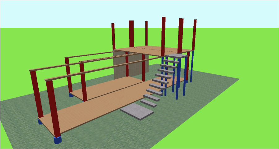
Figure 10 - Rear view with stairs and landings positions added
The “Structural - 2” file will model only the first floor and adds all the exterior walls, then adding the exterior door and the window openings, to see how much lateral structural support can be expected from the side and end walls. The ISBU walls are an important structural element so I want to keep my door and window cutouts to a minimum, preserving the structural integrity of the whole as much as possible.
The next series of pictures show how the Structure2 view has evolved with the structural elements of the design displayed clearly.
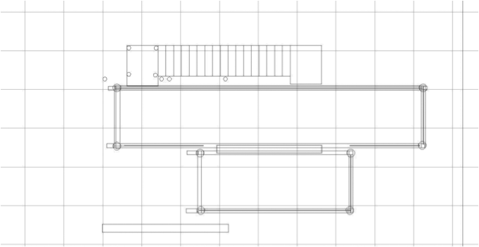
Figure 11 - The Plan View
Although it is in black and white you should be able to make out each elements. Later it will be necessary to label items, or place them on a schedule for reference and additional clarity. Following the plan view will be two perspective angles that show the same information as the plan view.
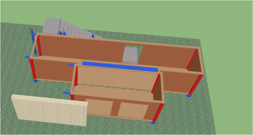
Figure 12 - Structure2 in perspective view
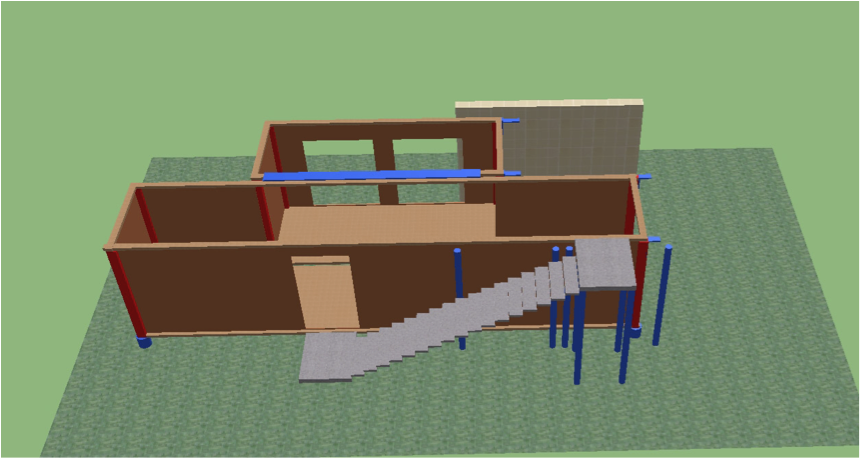
Figure 13 - Second floor perspective view
The second story floor plan will be represented in a file called Structural - 3 that will repeat the above steps for the second story.
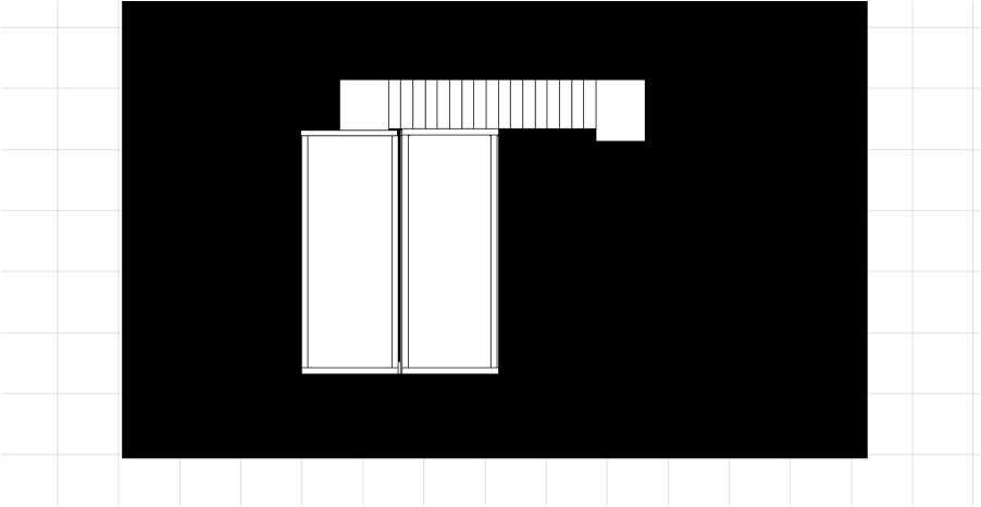
Figure 14 - Second Floor Plan View
Figure 15 - Second floor perspective views of structural elements.
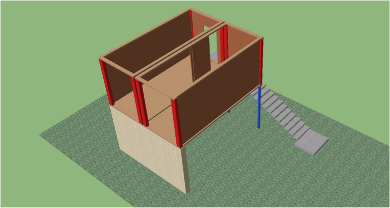
Figure 16 - Walls added to second floor
The Information entered into the CAD program in Stage 1 will serve as the basis for further development of the structural plans.
The next stage will provide the basis for your architectural drawings by developing the interior space further with interior walls, doors and cabinetwork. Again, there will be a file for each of the two floors. We can start these plans by copying the structure from the file Structural2 to a file named Achitectural1. Once Architectural1 is open you can remove or delete the structural elements, if necessary, to make the architectural elements more visible. I’ve started on the first floor by adding the bathroom fixtures, water closet, shower and vanity as well as a wall and door to enclose the bath. In the kitchen I’ve added the refrigerator, sink and cabinets. The toilet, shower and kitchen sink have been located on the rear wall to facilitate the waste plumbing, which will all fed to a waste stack located by the stairs. The upstairs bath will be located directly atop the first floor bath.
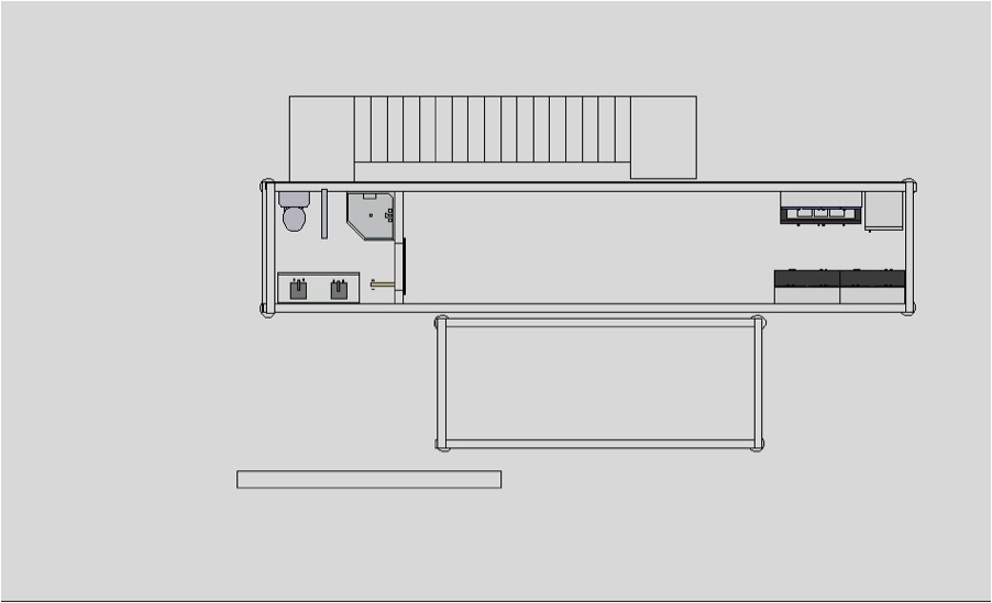
Figure 17 - Plan view of kitchen and bath features
The next two images show the kitchen and bath in perspective view. While I worked on the kitchen and bath I find it easiest to reduce the exterior wall sizes to 1 foot high. This allows a more complete view of the room and the walls can easily be brought up to full height again at any time.
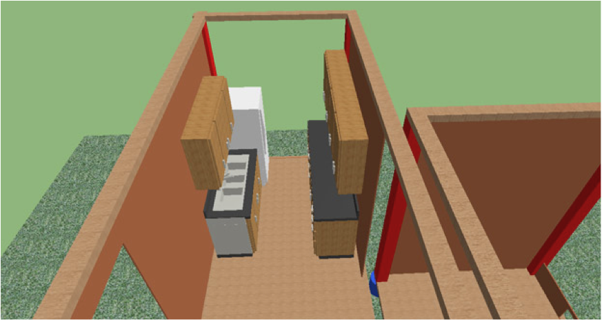
Figure 18 - Perspective view of kitchen with end wall dropped.
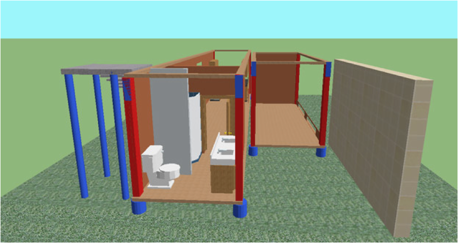
Figure 19 - Perspective view of bath through cargo door opening
Once the interior features are completed you can model the walls that will need to be built to take the place of the removed cargo doors. These walls can be framed in wood like a traditional exterior wall and they are a convenient place to add doors and windows without compromising the structural integrity of the exterior walls. In this example this will mean one wall with a window for the bath in the 40’ container and another wall with an entry door for the ground floor 20’ container. Additionally, we can add the sliding doors on the long wall of the 20’ container.
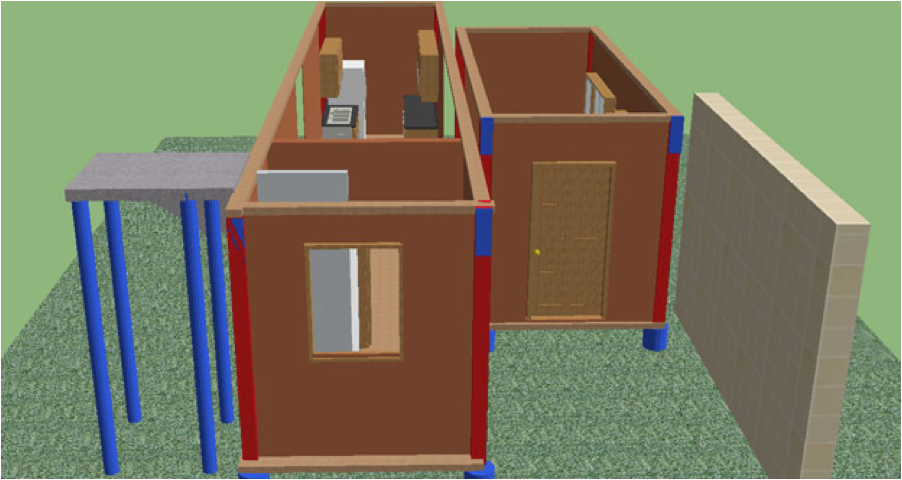
Figure 20 - Ground floor perspective view with walls in place
While the ceiling has still to be added, the major architectural elements are all included now, interior walls, windows and doors. The landing to the stairs will not have a door, but one could easily be added if desired. The steps for the second floor are the same; add the fixtures like the water closet, and sink, and then the interior walls that make up the bathroom and closet.
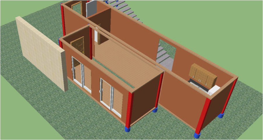
Figure 21 - Ground floor perspective top view with walls in place
The upper floor presents some challenges in the engineering department. While it would be nice to just have one big open floor, it would be unwise to just remove all 20 feet of ISBU wall to joint the containers as this would leave the roofs with no support at all, which would cause sagging. To solve the problem I have left most of the walls intact, allowing only two 4-foot openings, With the ISBU walls intact at both ends and a segment in the center, the roof should have adequate support. As you can see in the following plan view, the result is a private sleeping area with room left for a sitting area as well. In addition of course there are a bathroom and 2 closets.
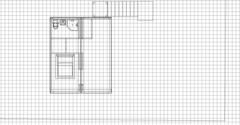
Figure 22 - Second floor plan view
The bath is placed directly above the bath on the first floor to simplify the plumbing. By having the waste stack rise outside the rear wall right next to the stair landings it will be easy to connect all the plumbing fixtures for the bathrooms with very short pipe runs. Because the upper floor is slightly offset from the ground floor access to cut openings for the pipes is available and should present no special problems. The white walls represent the wood framed interior walls and the brown walls represent the container walls.
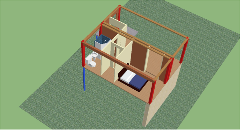
Figure 23 - Second floor perspective view
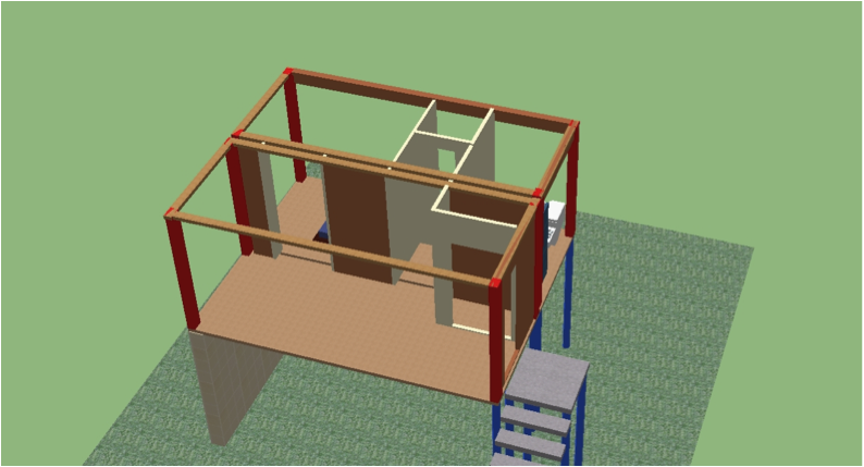
Figure 24 - Second floor reverse perspective view
Now that the interior elements have been added it is time to add the exterior walls, unite the upper and lower floors, and then move on to Stage 3, adding the roof trusses, finishing the exterior stair framing and adding the exterior cladding. The next 2 views are of the two floors enclosed, with walls and ceilings, and combined as a single structure
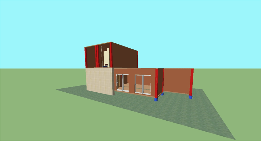
Figure 25 - Perspective view of entire structure
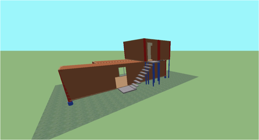
Figure 26 - Perspective view of rear of entire structure
Solving the stairway problem.
While modeling the roof for the structure I encountered a problem with the exterior staircase, as it exists in the plan above. Specifically, enclosing the stairs would require a wall that would raise the full height of both stories, on both sides of the stairs. The enclosure would require a roof high enough to allow a person to ascend the stairs, so it would block drainage from a portion of the first floor roof as shown in the next image, not a good design.
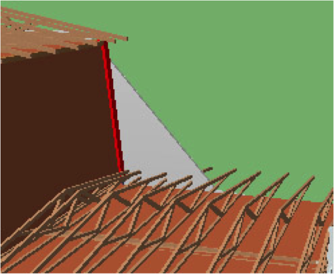
Figure 27 - Stair enclose would block roof drainage
While I had originally considered an interior spiral stairway, the lack of interior space made me opt for the exterior stairs, but this problem with drainage puts that concept to rest.
The best solution I can arrive at is to utilize the spiral staircase, but move it to the exterior of the house. This solves the drainage problem because the framing to enclosing the stairs won’t extend to the same extent as it would with the straight stairs. Being more compact, the spiral stair design will require considerably less wall framing as well. So, back to the drawing board, for a revision, as seen it the next image. The spiral stairs are a little tricky to model but the full instructions are included in the DW tutorial. I started with a foundation pad and modeled the stairs in the center and then added the corner framing before grouping the whole thing together as one unit, which will enable me to move it around in one piece if necessary. I have also modeled the three different wooden roof trusses in the same manner, making the individual components and then uniting all the pieces into one truss, which can then be easily duplicated.
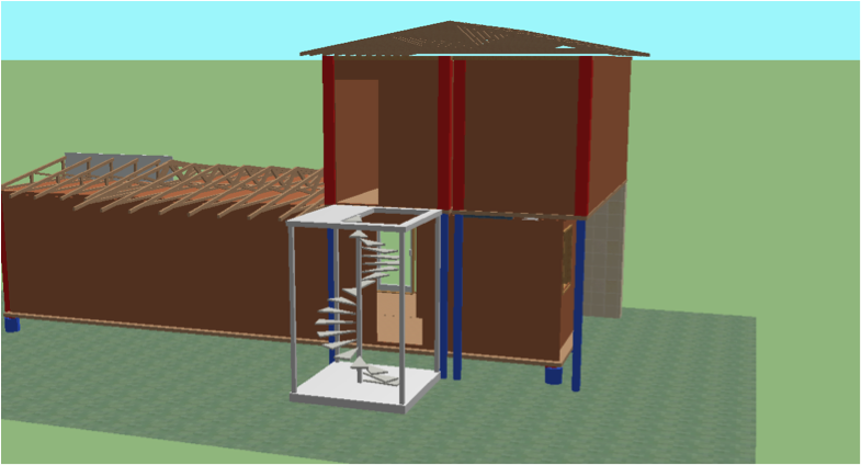
Figure 28 -Revised stair design
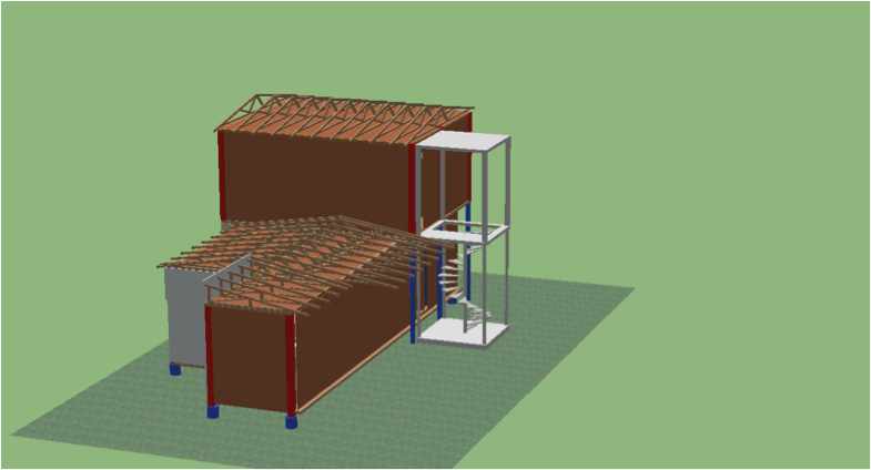
Figure 29 -Second floor stair landing
There are a couple of other corrections that need to be made as well. The entry door has been pushed out to align with the wall supporting the upper floor. I’ve also determined that there is a need for additional pier supports underneath where the two ground floor containers meet. Because these walls have been mostly removed I want to make sure there is sufficient support here.
Originally I had planned to utilize the space under the original stairs for utilities such as electrical service, waste stack and the water heater. With the new stair design some modifications will need to be made to that layout. This can easily be accomplished by extending one wall of the stairway enclosure to allow room for these mechanical components.
With these minor changes made we can go on to adding the exterior cladding and the roof itself.
For these final steps I've switched to a program called MAYA. This is a professional rendering program used by game designers. While it's not much good for floor plans or architectural design work, for showing what the finished product looks like it's hard to beat. I've changed to a bowstring truss design which will give a barrel roof look to the structure. Because I'm visualizing an aluminum composite exterior cladding I've coded the panels.
The perspective is a little off, in order to fit the on the page. Click on the image for the larger view with the correct perspective to scale.
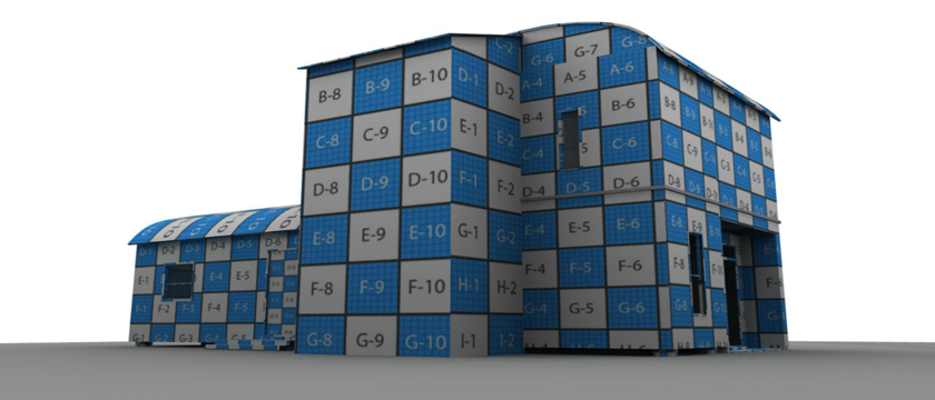
Figure 30
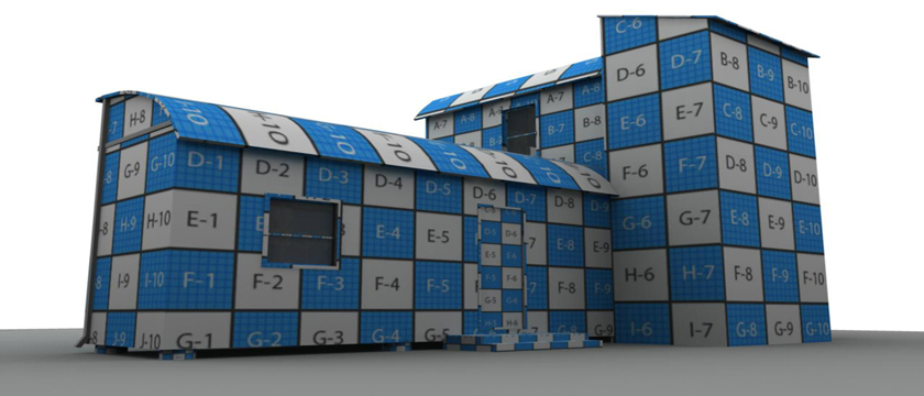
Figure 31
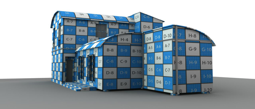
Figure 32
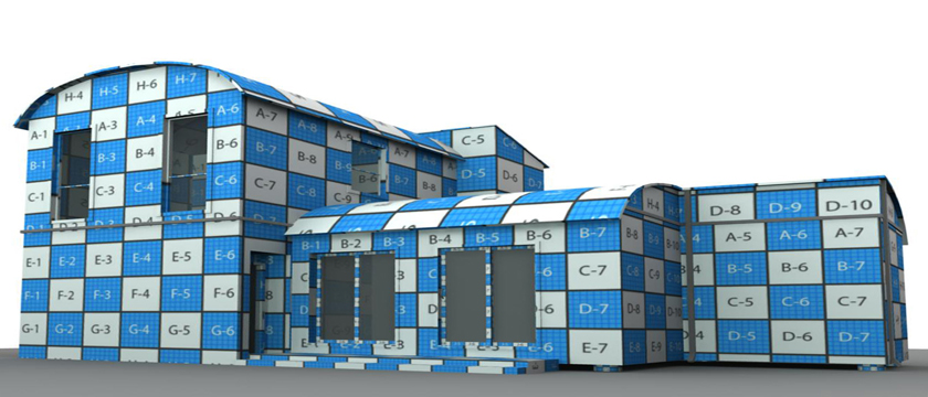
Figure 33

Figure 34

Figure 35
Scroll down for next chapter