
Establishing the design criteria is the first step in determining the design loads for an ISBU structural engineering analysis. Due to differences in climatic, geographic, and seismic conditions across the country, logic dictate that regional/ local data will form the primary inputs when determining your design criteria and load capacities. As an example, a home in Vermont will require a roof that can carry a substantial snow load, while a home in Arizona will not. A home in California will have to be designed to absorb seismic loads that a house in Nebraska will probably never face.
The International Residential Code is specific on the climatic and geographic design criteria in the following categories. It's most likely that your local jurisdiction will have incorporated the pertinent local factors into the code when they adapted it. If the locals only adopted the code, un-adapted, you may have to consult the appropriate figure or diagram in the IRC to arrive at the values for your region.
Wind Speed (mph)
Seismic design category
Weathering
Frost line depth
Termite
Winter design Temp
Ice barrier underlayment
Flood Hazards
Air freezing index
Mean annual Temp.
Ground Snow Load
The unique design criterion of your location reflect the critical local variables as specified by the IRC. As an example, Phoenix, AZ, which has adapted the 2006 IRC for their jurisdiction, specify the following design criteria.
Wind speed – 90 mph
Seismic design Category – B
Weathering – Negligible
Frost line dept – 0
Termite – Moderate to heavy
Decay – none to slight
Winter design temp – N/A
Ice barrier underlayment – N/A
Flood hazard – See Phoenix city code
Air freezing index – 0
Mean annual temp. – 70 degrees
Obviously the Arizona climatic and geographic conditions are unique to its region and vary considerably, from say, conditions in the New England region. Consult your local building code for the relevant data for your region. Buildings must be engineered to safely resist the structuralactions and load effects resulting from the unique load combinations specified in the design data for your region.
As you design your structural components, systems, and connections keep in mind that they must be designed in such a manner that a continuous load path is present and capable of transmitting lateral and vertical design loads through the structure to the ground. The design criteria will provide you with the load limits that must be met. The next step is for you to make sure that your design will provide or meet those load limits via the load paths of your design.
Loads and load paths are two crucial elements in gaining building department approval. The 2006 IRC states, a properly engineered building will “provide a complete load path for the transfer of all loads, from their point of origin, through the load resisting elements, and down to the foundation.” In essence loads and load paths are the very core of your design. So lets get a handle on understanding what they are and how they influence design.
The concept of loads and load paths is simple enough to apply to traditional raised platform wood framed construction. As a nation we have been building this type of structure for generations and the information acquired over the years to engineer such a structure is readily available in the form of standardized framing guides for wood, and uniform material standards that are recognized by everyone involved in the building trades, from the code writers at the ICC, to the building inspectors, to the contractors.
Follow the guidelines in the tables of the IRC and your wood framed home will be deemed safe for occupancy. Part of the beauty of wood frame construction is that the engineering was done long ago and converted into the standardized tables and charts you find in the IRC and elsewhere. That is one reason why wood frame construction is the most common and cost effective ways to build a home in the USA, no custom engineering is required.
But this type of construction is a complex system, requiring considerable skill and labor to assemble. For years designers and architects have dabbled with a simpler, modular, approach to building in an effort to reduce complexity and thereby costs. But when construction involves non-traditional materials the standardized guides are of little or no use, and the additional cost of engineering for loads and load paths become vital to proving the structure safe. Fortunately the IRC recognizes that alternative building methods do exist, or may be developed, and provides for them.
Alternative Standards for other Building Materials: In the case of steel as an alternative material the IRC references the AISI Cold Formed Steel Standards as being permitted, subject to the limitations of the IRC.
Another section of the IRC you must be aware for if planning an ISBU structure is
Which states,
“When a building of otherwise conventional construction contains structural elements exceeding the limits of section R301 or otherwise not conforming to this code, these elements shall be designed in accordance with accepted engineering practices. The extent of such design need only demonstrate compliance of non-traditional elements with other applicable provisions and shall be compatible with the performance of the conventional framed system.” (Italics mine).
This section is good news for the ISBU builder because the ISBU IS designed and built in accordance with accepted engineering practices and IS certified as such by the International Standards Organization (ISO). When drawing up plans and seeking permits don’t refer to your ISBUs as shipping containers, it’s better to present the ISBU as a “pre-engineered steel structural element” that is merely incorporated with traditional construction, you will now be talking a language the city engineers understand.
ISBUs as Engineered Elements
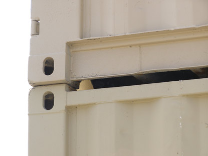
It should now be readily apparent that stacking ISBUs in any other manner then the how they were designed to be stacked immediately leads to the alteration of the intended load paths. The consequence of that, unfortunately, is that the ISO testing data must be re-analyzed and adjusted to reflect anticipated variations from the testing standard.

Scroll down for next chapter