While the Engineering Section deals with the structural aspects of containers in more depth, it is worthwhile to review, here in the design section as well, some of the more important general concepts of successful shipping container home design. The success of your design will be in direct proportion to how closely you follow the following guidelines.
Follow these rules while designing with shipping containers and you will be assured the most efficient material usage, lowest costs, and a lack of unanticipated problems.
Foundations:
Of the 3 major foundation systems in use today, the pier foundation is the most ideally suited for shipping container construction. Anchoring the corner fitting of each container to a foundation pier takes efficient advantage of the container's inherent load paths and floor strength while keeping concrete costs to a minimum. Additional piers can be positioned anywhere necessary to support additional load points as necessary. Piers and pilings are also the preferred foundation system in areas prone to hurricanes and flooding since they raise the structure up out of the path of still or moving water. In addition, pier foundations are a relatively easy project when compared to a slab or perimeter foundation, and they use much less concrete.
The shipping container's corner fittings allow you to attach them to the piers by incorporating a metal plate imbedded atop the pier that you can weld the corner block to, or, you can take the pier foundation concept one step further by incorporating a shipping container corner lock atop the pier as an ISO tested attachment system which will securely lock the container to the foundation.
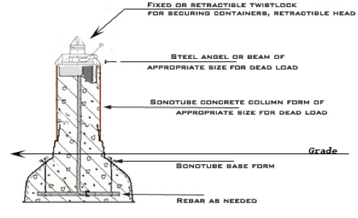
For a one story structure, or one-story of containers with a second story of traditional framing, a 12 inch diameter pier, with anchoring points 12 inches above grade should suffice. In cases where large sections of side wall are to be removed additional piers can be utilized approx. every 10 feet to support the lower side rail, and columns placed directly above the piers, to give additional support to the roof. The design criteria for your specific region’s climate and soil conditions will determine how deep below grade your piers will need to be.
The roof of a shipping container is not adequate as a residential roof or ceiling. The single layer of steel will be prone to condensation, is noisy in the rain, and lacks an adequate slope for rain run-off. In anything but the most temperate climate the steel roof will act like an oven in hot weather and a freezer in cold weather.
In your designs you should anticipate the need for the addition of an exterior roof consisting of roofing rafters, topped by a sheathed steel roof of appropriate slope and strength for the rain and snow load conditions of your region. The regional roof design parameters as they relate to snow load and runoff will be found in your local building code.
Leave the container's roof panels intact, cutting or removing them will seriously weaken the entire structure and add to your engineering costs. Your design will be most effective when you leave enough height between the container's roof and your framed roof to accommodate necessary insulation and ductwork, which will save ceiling height.
The upper beams which supports the sidewall panels and the roof panels has no real strength of it’s own. The C shaped beam simply acts as a cap to the side corrugated sidewall panels and attachment point for the roof panels. Alone, this beam cannot support it’s own weight, so plan accordingly.
The interior ceilings can be framed with 2x4s and drywall but the weight and the loss of approximately 4” of ceiling height would argue against it in my opinion. A lightweight suspended ceiling could be an option, or precisely cut ACM panels could be used to make a nice, slightly arched ceiling, suspended between walls by the tension of the arch, adding a parallel joint extrusion will give a truly finished look.
The dimensions of a shipping container will allow a smart designer to be very frugal with materials. The fact that the the container's exterior dimensions are 20 or 40 feet long and 8 feet wide dovetails nicely with the standard dimensions of most sheet type building materials. The standard dimension is 4’ x 8’ for items like plywood, drywall, paneling, and similar sheet goods. Some materials, like drywall, are also available as 4’ x 10’ and even 4’ x 12’ sheets. Conveniently, this allows an even number of material sheets (10, 5 or 2) to completely cover any of the 3 exterior or interior walls of a container, without any (or minimal) cutting and resulting waste.
Waste and material costs can be kept to a minimum if this concept is adhered to in the overall design. For example, when you position containers next to one another but staggering them, resulting in the ends being offset, such as when a 20’ container is placed next to a 40’ container, try to keep the resulting short walls an even size, like 2,4,6,8,10 or 12 feet. The diagram below offers a visual explanation.
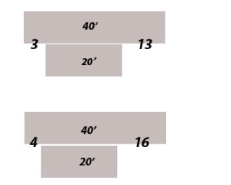
As you can see in the diagram, if choose an offset of 3’ and your material is 4’ wide it will be necessary for 1’ to be trimmed off of a whole panel. When you work around to the 13’ side you will have to use 3 whole sheets (12’) and then utilize the 1’ piece of scrap to complete the job. The result is only one extra cut and one extra joint in this case, but it’s still extra labor. The same issue will apply to the Interior drywall as well. An extra cut, an extra joint, more taping, more compound, more sanding, etc, etc. Applying this concept to exterior and Interior walls and anywhere else possible will result in a smart design that avoids unnecessary labor and material expenses.
There are several issues related to container floors that need to be explained.
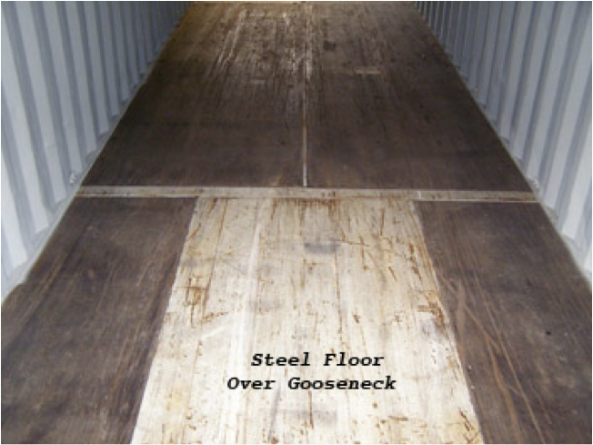
The factory floor of a typical shipping container consists of steel joists welded to the side rails every 12 inches. These joists may be T or J shaped, or some other profile. On a 20’ container there will be forklift pockets built in among the floor joists and on 40’ containers you may have a recess under the front end called a gooseneck receiver, which allows attachment to a chassis. The gooseneck allows the containers to lie lower, and therefore to be of taller, like a high cube’s 9’ 6”. But the down side is that the interior of the gooseneck area is steel rather than wood, along with a center spine of approx. 1.5” down the center of the flooring as in the photo below.
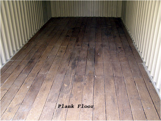
The old days of teak planked floors in containers are pretty much over. Even if you were to find a teak floor, the condition won’t be anything to write home about. It will be gouged and stained, show uneven gaps between the planks, and usually have at least some warped planks.
The plywood floors are for the most part in similar condition, minus the warped planks and gaps. It’s easy to see why the marine plywood was adapted to replace planks. Another issue with both types of wooden floors is the manufacturer's practice of impregnating the wood with insecticides. You can deal with the insecticide a couple of ways, but it is NOT a good idea to sand these floors, as it will raise a dust infused with a brew of chemicals. A better and more effective solution, for those who cannon tolerate insecticides at all, is removal and replacement, a simple and relatively inexpensive job with the plywood floor but impractical with the plank floor. If you prefer to utilize the pesticide to your advantage it can be contained on the habitable side and left exposed underneath where the insects actually are. The solution is to seal the interior floor with 2 or 3 coats of good quality water based sealer that will soak deep into the wood. Then apply a new sub floor atop the existing wood. This new sub floor will be needed anyway to gap spans in the floors between containers as explained next.
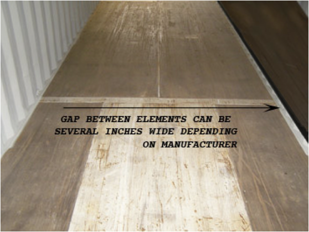
Containers are designed to stack closely together but when the corner columns/corner fittings of two containers are butted up tightly together there remains a gap between the bottom side rails of the two containers, and a still wider gap between the two walls themselves. If you remove both walls separating the two containers the gap between the floors is wider still. This gap must be sealed up, insulated and leveled between the two elements.
Once your containers are all positioned and locked down on their piers you can begin to remove wall material to allow traffic flow as specified in your floor plan. Be conservative in this, the bottom rail has very little strength left when the side wall is removed; it will only span about 10’ on its own. Once the wall sections are removed you will quickly realize that the gaps between the containers can be quite large, and the floors may vary some in elevation on either side of the gap.
Begin by sealing the gap itself with expanding foam or insulation board. Up above, the additional layer of floor sheathing floats between the two elements, allowing you to adjust and align with both floors or tie in adjoining floors of traditional framing. Details of this are in the Detail Drawings section.
When seasonal temperatures cool outdoor air, it’s relative humidity drops, while warmer interior air is able to hold more moisture, creating a difference in vapor pressure. This difference in pressure causes the moisture vapor to migrate through wood framed walls and equalize with the dryer air outside. This is called diffusion. If this warmer, moister air passes through a barrier with a cooler surface, the water vapor will condense and form water droplets. The point where the water condenses is called the dew point.
Poorly designed vapor and air barrier systems can be more detrimental to your structure than allowing water to freely migrate through a wood framed house, which was the norm until about 30 years ago. Trapped moisture will degrade the efficiency of you insulation, cause wood rot and encourages the growth of mold or mildew. Therefore, in traditional wood frame construction vapor retarders/air barriers are used to stop or slow the diffusion of moist air through walls and ceilings.
A vapor barrier typically consists of a 4-mil polyethylene installed on the warm side of the wall to serve as both an air barrier and a vapor retarder in walls, ceilings and also under floors with crawlspaces. Placement of vapor retarders is dependent on the climatic zone where you are located. In colder climates winter condensation is most common and will occur when the interior of the home is warmer than the exterior air. This often manifests itself by water condensing on the interior of the cooler widow panes when warm interior air passes over them, or toilet tanks sweating when re-filled with cold water.
In the gulf coast area, where outdoor humidity levels are highest no humidity can transfer from the interior to the exterior because, as you remember, vapor pressure, or humidity transfer is always from the warmer side to the cooler side. So here vapor retarders go under the exterior siding, rather than under the interior drywall, to keep moisture from flowing in rather than out.
A shipping container in its raw state is an ideal conduit for condensation. To demonstrate, consider an ordinary, unmodified cargo container on a warm summer day. The steel wall’s temperature will be nearly identical if measured on the exterior and interior sides. Now turn on an interior air conditioner to cool the space. Vapor pressure will draw warm air up and in from the floor area and cause the warmer air to transfer moisture to the cooler air. As the interior air gets cooler the interior sides of the steel walls cool just slightly as well, and soon condensation forms outside as warmer exterior air transfer moisture to the cooler walls. To maintain an equal temperature in the steel walls add interior and exterior cladding which will shield the steel walls from direct sunlight and wind on the exterior side and allow for an even warming and cooling of the steel, which will avoid condensation.
Fiberglass is considered the norm for insulation in a construction industry ruled by contractors, builders, code inspectors and R ratings. But, in the world of container construction you will hear a lot about spray on ceramic coatings, often mentioned as a substitute for Fiberglass insulation because they are easily applied to the exterior surface of the container While the evidence that ceramic coating insulating is an effective alternative to traditional batt insulation is questionable, the bottom line is that these ceramic coatings have yet to become code-approved and accepted as a sole means of insulating a home.
Perhaps in the future the demand for increased energy efficiency will push these products to the forefront in the consumer market. Until then, the best use of the ceramics will probably be as a part of a hybrid insulation system, utilizing ceramics sprays to actually prevent heat load in combination with batt insulation to meet code.
Ceramic coatings have been around for quite some time and are proven effective in preventing heat loss or gain. They accomplish this by preventing heat load, the key to insulating. The concept is quite simple, why use fiberglass insulation to slow the transfer of heat when you can just prevent the heat from ever loading onto the building in the first place? If the heat is kept off the structure to begin with, the fiberglass insulation becomes unnecessary. Depending on the compounds used, the ceramic spray has the ability to prevent heat transfer and heat loading onto a structure, meaning that heat will not transfer into or out of a building.
Fiberglass insulation, and the building codes, use an R-value rating, which assumes a heat load on the building, and measures the rate at which that heat is transferred. Ceramic coatings on the other hand are not given an R-value rating; they are measured by their emissivity, which is the ability to reflect heat and the amount of heat loaded on the surface. Fiberglass is rated in terms of thickness; six inches of fiberglass insulation might equal an R-19 rating while a 10 mil dry ceramic coating might offer an R equivalent rating of R-20.
As an exterior surface coating, insulating ceramic paints or coatings can be applied to the roofs and sides of a container. Ceramic coatings can be used on the interior of a home, too.
Most mechanical heat is Infrared heat, so ceramic coatings can be used to prevent heat loss from inside a building as well. A home interior coated in ceramic paint can therefore reduce energy costs due to heat loss in the colder months.
Sidewalls & Loads: When designing with shipping containers it is good practice to remove as little of the corrugated sidewall as possible. Always leave 3 to 4 feet of undisturbed sidewall adjacent to each corner post because the sidewalls act as shear walls, having a structural relationship and contributing to the strength of the corner posts. Remember that much like a skyscraper, the steel skeleton of a container’s posts and beams supports the majority of the load and provides a path down to the foundation or ship deck. If your plans will involve stacking the containers on top of each other this concept becomes even more critical. As a simple rule of thumb - the more side wall you remove the greater the chance you will need to add expensive structural steel supports to regain lost load capacity. More information is available in the Engineering Section.
Oil Canning: Oil canning is perceived as waviness across flat areas of sheet metal. It is more common in the lighter metal gages and in panels that have broad flat areas. There are several causes, most commonly, thermal forces, such as heat from a torch, or even the sun moving across the sky. In the case of container construction, oil canning is most often the result of cutting openings in the corrugated walls with a torch. The high heat distorts the metal and, while not a structural problem or a defect, it can make the rough openings for windows and doors irregular causing problems with fitting, not only the doors and windows, but the trim as well.
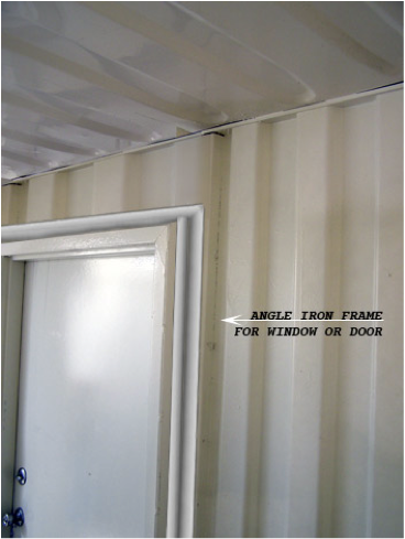
While oil canning cannot be totally eliminated, the best way to minimize it is, prior to cutting, spot-weld 2x2 steel angle iron around the exterior perimeter of the planned cut outline. This will reinforce the straightness of the wall after the cut has been made as well as providing a ledge that can more easily accept the window and act as an attachment point for the trim, drywall, etc. It is also possible but time consuming to use a Sawz-All or other reciprocating type saw be used rather than a torch to avoid the distorting heat and allow the control needed for a nicely finished opening.
Joining the containers: Once you have each container craned into position and secured onto the pier foundations, adjacent units are welded to each other at the top and bottom corners. By welding the corner attachments together you are creating a bigger strong steel box that just a single container. Very little welding is needed because the incredible strength of the columns and corner attachments prevent any stress such as twisting or other movements from migrating as far as the welds and weakening them. Another option is to attach the units together using traditional cargo handling equipment as used on cargo ships. This allows the structure to be disassembled with hand tools rather than a torch. Either way, the result if designed correctly, is an immensely strong structure that goes up in almost no time at all.
Exterior Doors & Windows: The use of an angle iron frame as cure for oil canning results in a nice neat opening for a pre-hung door or window in an exterior wall. A pre-hung steel exterior door is a natural choice for strength and security as well as its compatibility with shipping container construction. Choices in window materials and designs are nearly endless, but regardless of the type door or window selected, check the manufactures specs for exact offsets and rough opening size. And be sure to consider these factors as you plan your door and window trim details.
Many pre-hung exterior doors and windows are sized for a 6” thick wall, so the container wall profile of your design will have to consider your design’s overall exterior wall thickness and trim accordingly. These issues are usually resolved when doing the section drawings.
If the design guidelines of the engineering section are followed there will not be any interior walls that bear a load, they will all be partition walls constructed in the traditional manner. The IRC wall framing schedules will be your guide here.
As explained in the engineering section, cantilevering results in loads being placed where they weren't’t intended on the container, as well as making the connection of the units into a much more difficult project. While cantilevering isn't impossible it does require additional reinforcement as described in the Building Section.
It’s generally a bad idea to bury a shipping container. The walls and roofs aren't designed for the extreme soil pressures that will result and the corrosive effects of soil will eventually destroy even a Coreten steel container. If you want to go to the trouble of providing retaining walls to ease the side load it's doable but the expense would seem to be excessive.
Scroll down for next chapter