
Your plan set will include electrical drawings, which will show the various electrical and other wiring systems of the structure. These drawings are numbered sequentially and show an “E” prefix. They usually include an electrical power plan and a lighting plan but can also include security systems or fire alarm systems. The format is a plan view with details and schedules for clarification.
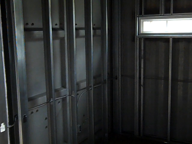
While the power plan will show the panel requirements and circuits, and the lighting plan will show the location of lighting fixtures, how it all comes together is usually left up to the electrician’s expertise. But the electrical wiring of a shipping container cannot be completely done in the traditional manner. In wood frame construction the electrical wiring usually consists of Romex, or some other type of non-metallic sheathed electrical cable, which is strung through holes drilled in the centers of the wall studs to accommodate the run of wire from the electrical panel or junction boxes to the switches, receptacles, and service equipment.
Within a container structure electrical receptacles and switches for the interior walls can be wired in the traditional manner with Romex or you can choose to bring the power up to the walls through the floos via electrical conduit and then wire the wall itself in the traditional manner using romex.
In container construction an alternative way to wire the structure is to place all the wiring runs underneath the floor, utilizing the 12” crawl space. But, rather than using a flexible, vinyl sheathed electric cables we will borrow a commercial technique and use electric metal tubing, or EMT, and flex conduit along with junction boxes to complete the horizontal runs under the structure, with the boxes and conduit attached to the steel floor joists. This has several benefits; the metal conduit will protect the wiring from the elements, rodents and anything else that may attack it. Once all the conduits and the junction boxes are in place the wires for each circuit are pulled through for connection. This method also makes it much easier to add to, upgrade, or re-configure your wiring without tearing open the walls.

Vertical wiring runs from below the floor to switches and receptacles incorporate a vertical stub of EMT from the junction box coming up through the wood floor and curving in to continue the rise between the corrugations of the wall to the proper height for the switch or receptacle.
Begin with the floor cutouts for the electrical wall receptacles and switches. Mark the floor with the locations of each hole where the EMT will rise through the floor to each receptacle and wall switch. Mark as close to the steel edge of the floor as practical, paying attention to avoid floor joists. The EMT will need a slight compound bend to fit into the recesses of the corrugated wall, which will house the receptacle or switch box. Cut these 3/4" holes using a drill through the wood and steel making sure to miss the floor joists underneath. Make the holes large enough for the 1/2inch EMT, giving enough room to wiggle into position. Make the receptacle vertical runs 7" and the switch runs 52" above the final floor height. Seal any gaps between the EMT and floor with expanding foam.
Now, from underneath the unit, locate each piece of EMT and attach a 4 gang box directly beneath it, as close to the floor as possible while still avoiding the need to drill any cross members (if possible). Your choice of conduit here will make a difference. Flex conduit can make it easy to go over, under and around obstacles without any of the pipe bending necessary with rigid pipe. But you cannot pull as many wires through flex on a long run.
Once your 4 gang boxes are in place connect them, one to another as indicated by your electrician in his wiring plan. Pull the wires from box to box and up the appropriate EMT leading to each switch and receptacle. Leave plenty of wire for the finish work and enough slack in the boxes to allow additional wire pulls and pig tails in the future if necessary. Make special preparations for the upper floor units to have the circuit connection with the lower floor in place and ready to connect when the upper floor is lifted into place.
If you are designing a 2-story structure place your boxes and conduit before hoisting the containers into place. And be sure to consider an appropriate electrical connection such as an elec. gutter between the upper and lower containers. Once the upper containers are in place any e-boxes underneath are going to be inaccessible so do the wiring before placing them in position or revert to the traditional romex running through the walls on the second floor.
Make you electrician aware of this situation and he can design the wiring junction. Another alternative would be to design your upstairs floor with hidden traps, or an access door in the upstairs closet, that will allow you to access one or two of the main 4 gang boxes, this will allow you to pull additional wires or replacement wires if necessary.
Scroll Down For Next Chapter